Short answer: almost every India Mark 2 breakdown below ground comes down to a few worn rubber parts in the cylinder: two cup seals, two rubber seatings and three sealing rings. To replace them, a trained pump mechanic lifts out the rising main, opens the cylinder, renews the rubber parts, tests the cylinder in a bucket and reinstalls the pump. This guide walks through every step, based on the Installation & Maintenance Manual for the India Mark II Handpump published by Skat and the Rural Water Supply Network (RWSN) with UNICEF.
- What is below the ground
- When do you need to pull the pump?
- Tools, materials and spare parts
- Safety first
- Step 1: Remove the above-ground parts
- Step 2: Lift out the rising main
- Step 3: Open and repair the cylinder
- Step 4: Inspect pipes, rods and liner
- Step 5: Reassemble and bench-test the cylinder
- Step 6: Reinstall the pump
- Step 7: Test and record the repair
- Troubleshooting chart
- Preventive maintenance schedule
- Training videos
- FAQ
What is below the ground
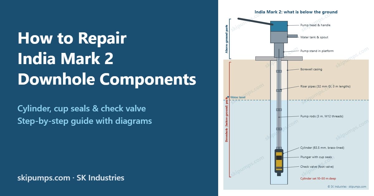
The India Mark 2 is a lever-action deepwell hand pump designed to lift water from up to about 50 metres. Everything that does the actual pumping is at the bottom of the borewell, out of sight:
- Riser pipes (the rising main): 32 mm galvanised iron (GI) pipes in 3 m lengths that carry water up to the spout.
- Pump rods: galvanised steel rods in 3 m lengths with threaded connectors, running inside the riser pipes and linking the handle to the plunger.
- Cylinder: a cast iron body with a 63.5 mm brass liner, closed at each end by a reducer cap.
- Plunger: a brass plunger with two nitrile rubber cup seals and an upper valve, moving up and down inside the cylinder.
- Check valve (foot valve): a one-way valve at the bottom of the cylinder that stops the water column falling back into the borewell.
Because these parts are deep in the borewell, the India Mark 2 is not a VLOM pump (Village Level Operation and Maintenance). Caretakers can do the monthly checks, but any downhole repair needs a trained area mechanic with the special tool kit.
When do you need to pull the pump?
Before lifting anything, confirm that the fault really is below ground. Three simple field tests from the maintenance manual need nothing more than a 20-litre bucket and a watch:
| Symptom | Most likely downhole cause |
|---|---|
| Handle is easy to push but little or no water | Worn cup seals, a disconnected pump rod, a jammed check valve, or the water level has dropped below the cylinder |
| Water comes only after many strokes (more than 5 after a 30-minute rest) | Leaking check valve or worn sealing rings, worn cup seals, or a leaking riser pipe joint |
| Less than 10 litres from 40 strokes | Worn cup seals, cracked or corroded riser pipe, or loose pipe joint |
| Red, brown or metallic-tasting water | Corroded GI riser pipes and rods (see corrosive water) |
| Chain folds on the down-stroke | Top rod too long, so the plunger is sitting on the check valve |
Also rule out the simple above-ground causes first: a broken chain, loose handle axle nuts or worn ball bearings can all be fixed without touching the rising main.
Tools, materials and spare parts
Special tools (area mechanic’s kit)
| Tool | Used for |
|---|---|
| Tripod with chain block (or pulley and rope) | Lifting heavy rising mains, typically 30–50 m settings |
| Lifting spanners (2 or 3) | Lifting shallower rising mains (about 10–30 m) by hand |
| Pipe clamp | Gripping the riser pipe for the chain block hook |
| Pipe vice | Holding the rising main on the pump stand while pipes are unscrewed |
| Pump rod vice (connecting rod vice) and rod lifter | Holding and lifting the pump rods |
| Chain support (chain coupling supporter) | Holding the chain and top rod while the pump head is removed |
| Pipe wrenches (2) | Opening and tightening riser pipes and reducer caps |
| Open-ended spanners: 17 and 19 mm (2 each); 16 and 18 mm for newer bolt standards | M10 and M12 bolts and nuts |
| Hacksaw, flat file, M12 die set, wire brush | Cutting and re-threading the top rod, cleaning threads |
Materials
Hemp fibre with grease, sealing liquid or PTFE (Teflon) tape for pipe threads; heavy-duty grease for the chain; emery cloth and clean rags; a 20-litre bucket of clean water for testing.
Spare parts to carry to every downhole repair
| Part | Qty per pump | Where it fits |
|---|---|---|
| Cup seal (drawing C2359) | 2 | Plunger assembly |
| Rubber seating, upper valve (C2360) | 1 | Plunger assembly |
| Rubber seating, check valve (C2364) | 1 | Check valve |
| Sealing ring (C2354) | 3 | Between cylinder and reducer caps |
It also pays to carry one spare riser pipe and one pump rod, a few pipe sockets and rod couplers, and ball bearings for the pump head.
Safety first
- Never put your fingers between the pump head and the handle. The moving parts can crush them.
- Always hold the riser pipes firmly or keep them clamped in the pipe vice. A slipping rising main can crush hands and drop the whole string down the borewell.
- Agree who does what before lifting, and talk to each other throughout.
- Use the correct tools. Improvised tools damage threads and cause accidents.
- Keep oil, metal shavings, rags and tools out of the borewell.
Step 1: Remove the above-ground parts
- Loosen the bolt and remove the pump head cover.
- Lower the handle and place the chain support under the chain assembly.
- Raise the handle to the top position. With two spanners, loosen the “Nyloc” nut, remove the chain anchor bolt and pull the chain out of the handle.
- Remove the bolts between the pump head and the water tank, and lift off the head. The chain passes through the hole in the bottom flange.
- Turn the middle flange 90°, lift the top rod by holding the middle flange, and fit the pump rod vice on the water tank’s top flange. Let the middle flange rest on the vice.
- Take off the chain support, unscrew the chain from the top rod, unscrew the check nut and remove the middle flange.
- Screw on the rod lifter, hold it firmly, open and remove the rod vice, then gently lower the pump rods until the plunger rests on the check valve. Unscrew the rod lifter.
- Remove the bolts between the water tank and the pump stand. Lift the water tank about 50 cm, clamp the riser pipe in the pipe vice and unscrew the water tank by turning the spout.
Step 2: Lift out the rising main
How you lift depends on the depth of the cylinder:
- About 10–30 m: screw a short piece of riser pipe into the water tank thread (or the top socket) and lift with two or three lifting spanners.
- About 30–50 m: the string is too heavy to lift by hand. Use a tripod with a chain block and a pipe clamp.
- Fit the pipe clamp on the riser pipe and tie it with a short rope to the chain block hook.
- Tighten the chain block until it takes the load, then open and remove the pipe vice slowly.
- Lift the string until the next pipe socket is about 0.5 m above the top flange of the pump stand.
- Re-fit the pipe vice and clamp the rising main securely.
- Remove the pipe clamp and unscrew the protruding riser pipe with two pipe wrenches.
- Lift the loose riser pipe by hand until the pump rod joint is visible, and unscrew the pump rod.
- Lay the pipe and rod on a clean surface (logs or a pipe stand), never on the ground. Repeat until the cylinder comes out.
- Unscrew the last riser pipe from the cylinder’s upper reducer cap, then disconnect the last pump rod from the plunger rod.
Step 3: Open and repair the cylinder
Clamp the cylinder gently, or hold it with pipe wrenches, and unscrew both reducer caps. Pull out the plunger assembly from the top and the check valve from the bottom, and remove the three sealing rings.
Plunger assembly
- Unscrew the plunger rod, then unscrew the plunger body from the follower.
- Lift off the upper valve and remove its rubber seating.
- Slide the spacer off the follower and remove both cup seals.
- Clean all brass parts. Check the upper valve and follower seat for wear or damage.
- Reassemble with new parts in this order: fit a cup seal to the lower part of the spacer and another at the top of the spacer, with both lips facing up. Push the follower into the spacer, place the upper valve with its new rubber seating on top, screw on the plunger body and tighten securely, then tighten the plunger rod.
Check valve
- Separate the check valve from the check valve seat and remove the seat retainer and rubber seating.
- Clean the seat and check it for cracks, chips or a worn sealing face.
- Assemble the check valve with the check valve seat, fit the new rubber seating and secure it with the seat retainer.
Step 4: Inspect pipes, rods and liner
While the pump is out, check everything, not just the part that failed:
- Cylinder liner: run a finger around the inside. Deep scratches or scoring will destroy new cup seals quickly; replace the cylinder if the liner is badly scored. Remove light residue with emery cloth.
- Pump rods: roll each rod on a flat surface to find bends; check threads and connectors. Replace bent or corroded rods.
- Riser pipes: look for rust, pitting, thin walls, cracks and damaged threads. Clean threads with a wire brush.
- Sockets and couplers: replace any with worn or damaged threads.
Corrosive water: fix the cause, not just the symptom
If the riser pipes and rods are badly rusted, the water is probably aggressive. RWSN’s Stop the Rot research found rapid corrosion of galvanised handpump parts to be widespread where groundwater is acidic, with a pH below about 6.5. Replacing rusted GI pipes with new GI pipes only restarts the clock. At these sites consider corrosion-resistant components such as PVC riser pipes with stainless steel couplings, PVC riser pipes with square threads or stainless steel cylinders and rods. For more on why part quality matters, see Why cheap hand pump parts cost more.
Step 5: Reassemble and bench-test the cylinder
- Check that the liner is clean. Clean the threads of the cylinder and both reducer caps and apply sealing liquid or hemp fibre with grease.
- Place the first new sealing ring in the lower reducer cap, insert the check valve assembly, place the second sealing ring, and screw the cylinder into the reducer cap.
- Slide the plunger assembly into the cylinder, place the third sealing ring, fit the upper reducer cap and tighten both caps with pipe wrenches.
- Bucket test: dip the bottom of the cylinder in a bucket of clean water and work the plunger rod up and down until the cylinder is full. Stand it upright and watch for leaks. Wait a few minutes for the outside to dry first, so surface water isn’t mistaken for a leak. If it leaks, tighten both reducer caps before taking it apart again.
Step 6: Reinstall the pump
- Lay the first riser pipe and its pump rod horizontally on the platform and connect the pump rod to the plunger rod.
- Seal the pipe thread (hemp and grease, sealing liquid or PTFE tape), screw the riser pipe into the upper reducer cap and tighten with two pipe wrenches.
- Lower the cylinder by hand until the pipe sticks out about 50 cm above the stand, then clamp it in the pipe vice.
- For each next length: connect the pump rods first, then the sealed riser pipe; lift slightly, remove the vice and lower. Use the chain block and pipe clamp once the string gets heavy (typically after 5–10 lengths).
- If the water level has dropped since the last installation, add one riser pipe and one pump rod so the cylinder stays under water in the dry season.
- Screw the water tank onto the last pipe, lower it onto the stand flange, turn the spout to the right direction and bolt it down with 4 × M12 bolts.
- Top rod length: if you have added or replaced rods, cut the top rod so that the plunger does not knock the check valve or the upper reducer cap. Mark it at the top face of the water tank flange, clamp it in the rod vice, wrap a cloth around it so shavings and oil cannot fall into the well, cut, chamfer and thread 40 mm of M12 thread.
- Refit the middle flange, check nut, chain coupling, pump head, chain bolt with a new “Nyloc” nut, and the cover, in the reverse order of Step 1. Grease the chain.
- Before closing the head, check that the rod moves freely (if not, a rod is bent), the chain coupling is fully engaged, all 8 flange bolts are tight, and no tools or rags are left inside.
Step 7: Test and record the repair
- Pump to refill the rising main. A 40 m setting needs about 100 full strokes before water appears.
- Keep pumping for another 100 strokes and check that the water runs clear, with no oil or dirt.
- Carry out the discharge test: 40 full strokes in about one minute should give at least 16 litres.
- Carry out the leakage test: rest the pump for 30 minutes and repeat. The difference should be no more than 2 litres, and water should appear within 5 strokes.
- Explain to the caretaker what failed and why, and record the date, fault, parts replaced and setting depth on the pump’s maintenance card.
Troubleshooting chart
| Problem | Possible cause | Remedy |
|---|---|---|
| Pump works easily but no water | Worn cup seals | Pull rising main, open cylinder, replace cup seals |
| Water level below cylinder | Add riser pipes and pump rods | |
| Check valve jammed open | Pull rising main, open cylinder, repair check valve | |
| Pump rod disconnected | Pull rising main, reconnect rods | |
| Delayed or little water | Leaking check valve | Replace rubber seating; check seat |
| Worn sealing rings | Replace all three sealing rings | |
| Worn cup seals | Replace both cup seals | |
| Leaking joints or corroded riser pipes | Replace damaged pipes; consider corrosion-resistant pipes | |
| Plunger jammed | Wrong or damaged plunger or cylinder parts | Open cylinder, check sizes, replace defective parts |
| Chain folds on down-stroke | Top rod too long; plunger sits on check valve | Remove head, check rod length, cut and re-thread top rod |
Adapted from the troubleshooting annex of the India Mark II Installation & Maintenance Manual (Skat/RWSN).
Preventive maintenance schedule
| When | Who | What |
|---|---|---|
| Monthly | Caretaker | Tighten the 8 flange bolts, handle axle nuts and chain bolt; grease the chain; repair platform cracks and drain; clean the surroundings and fence |
| Every 3 months | Caretaker with mechanic | Replace missing fasteners; investigate unusual noise; check the stand is firm; run the leakage and discharge tests (more than 10 strokes before water means the leak needs attention) |
| Yearly | Mechanic | Pull the pump; replace both cup seals, both rubber seatings and all three sealing rings, plus the head’s ball bearings, even if they still work |
Replacing rubber parts on a schedule, before they fail completely, is what keeps a community pump from sudden breakdowns. Keep good used parts as emergency spares.
Training videos
The Water, Engineering and Development Centre (WEDC) at Loughborough University has published a four-part training film, The Operation and Maintenance of the India Mark II Handpump:
Frequently asked questions
How often should India Mark 2 cup seals be replaced?
The maintenance manual recommends replacing the cup seals, rubber seatings and sealing rings once a year as preventive maintenance, even if they still work. Sandy or silty water wears them faster.
Can the village caretaker repair the cylinder?
No. The India Mark 2 is not a village-level maintenance pump. Caretakers handle monthly checks and greasing, but pulling the rising main and opening the cylinder needs a trained mechanic with the special tools.
How many people are needed to pull an India Mark 2?
Plan on a mechanic plus at least two helpers: one to operate the lifting spanners or chain block and one to hold and unscrew the pipes and rods. Deeper, heavier strings need more hands.
Which way do the cup seals face?
Both cup seals are fitted with their lips facing up, towards the pump head, so the water column above the plunger presses them against the liner.
Why does my pump need many strokes before water comes?
The water column is draining back overnight through a leaking check valve, worn sealing rings, worn cup seals or a leaking riser pipe joint. If more than 5 strokes are needed after a 30-minute rest, the leak should be investigated.
Why is the water red?
Red or brown water usually means the galvanised riser pipes and rods are corroding. Replacing them with corrosion-resistant PVC riser pipes and stainless steel parts is the lasting fix.
Need genuine India Mark 2 spare parts? SK Industries supplies cylinders, plunger and check valve kits, rubber parts, riser pipes and rods, plus corrosion-resistant PVC riser pipes with SS couplings and stainless steel components. See the India Mark 2 hand pump page or send an enquiry.
About this guide
This guide was written by Sharad Jhunjhunwala for skipumps.com (SK Industries).
Sources
- Skat / RWSN with UNICEF, Installation & Maintenance Manual for the India Mark II Handpump, edition 2008
- Rural Water Supply Network, India Mark II – Handpump Technology
- K. Danert (2022), Stop the Rot: handpump functionality, corrosion, component quality and supply chains, Ask for Water GmbH, Skat Foundation and RWSN
- WEDC, Loughborough University, The Operation and Maintenance of the India Mark II Handpump, Parts 1–4 (video)
Diagrams © SK Industries. This guide is for trained hand pump mechanics. Always follow the procedures of your water authority or programme.